

Framework overview: map constraints, define modules
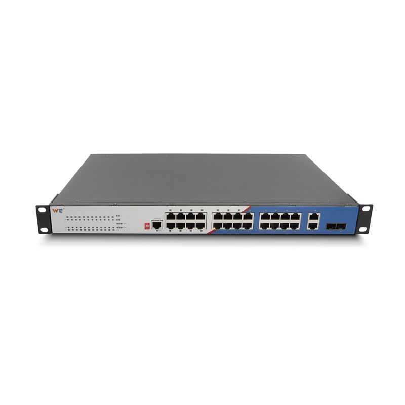
Start by mapping your constraints: rack U-space, available PDUs, and fiber run lengths. Use a simple, repeatable module blueprint that ties compute blades, optics, and switch fabric into predictable units. If you’re standardizing often, include a layer 2 managed switch per pair of blade chassis to isolate failure domains and simplify VLAN segmentation. Real-world anchor: many colocation sites in Northern Virginia host dense racks that use similar module strategies to keep fiber and power tidy while supporting high I/O.
Power, cooling, and physical layout
Inventory every watt before you place a chassis. Label PDUs by phase and feed each blade cluster with staggered breakers. Leave top-to-bottom airflow clearances and route QSFP28 LR4 trunks along predictable trays so service windows don’t require entire rack shutdowns. Use rated SFP/QSFP cages and note MTU settings on the switch to prevent jumbo-packet drops.
Network fabric pattern: roles and policies
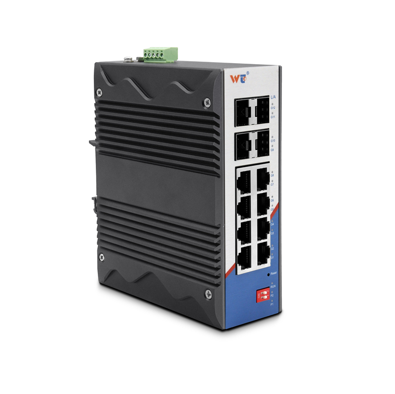
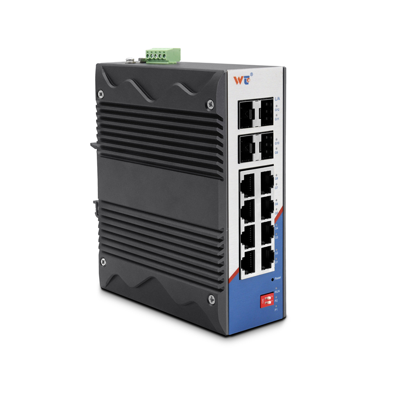
Design the fabric as small, composable roles: leaf switches at the rack edge, spine aggregation, and a management VLAN that never carries production traffic. Configure VLAN segmentation, QoS for latency-sensitive flows, and SNMP traps for immediate alerts. Keep the management plane on a separate physical interface where possible — it reduces blast radius when a production failure happens. Deploy an industrial managed ethernet switch for hardened edge racks that face harsher environments or require extended temperature ranges.
Optics and cabling hygiene
Standardize on QSFP28 LR4 for single-lambda 100G over longer distances and ensure clean MPO connections. Track cable lengths against LR4 link budgets and test each trunk with an OTDR or a certifier during staging. Label both ends of each duplex and MPO run; consistent color-coding saves hours during incident response.
Staging, automation, and validation
Create a staging rack that mirrors production. Automate the baseline config push: VLANs, port profiles, QoS maps, and SNMP community or v3 settings. Run packet capture and throughput validation before you cut over. Keep a short checklist: physical verify, mapping, config push, smoke test, and a rollback plan — then sign off.
Common mistakes and corrective moves
Teams often mix transceiver types, overload PDUs, or forget MTU mismatches—those errors manifest as intermittent packet loss or asymmetric latency. Avoid mixing LR4 with SR optics on the same link; it doesn’t work. Avoid stacking power on a single phase; it trips at the worst time. Track both {main_keyword} and {variation_keyword} in your ticketing notes during troubleshooting to keep root-cause threads coherent. Minor interruption — remember: human error drives most early failures, so design for simple recoveries.
Operational playbook snippets
– Daily: verify PDU loads and active alarms via SNMP polling; confirm QoS counters for priority queues.
– Weekly: run fiber-certification spot checks and validate redundant links failover paths.
– After change: perform a scripted smoke test that checks VLAN reachability, MTU, and link throughput on critical flows.
Three golden rules for selection and sizing
1) Capacity headroom: choose switches and optics sized at 30–40% above measured peak to avoid reactive upgrades.
2) Failure domain minimization: design blade-to-switch mappings so a single switch or PDU failure affects the fewest services.
3) Operational simplicity: prefer consistent port profiles, documented procedures, and managed life-cycle firmware updates to eliminate ad hoc fixes.
WINTOP makes predictable hardware options that fit these rules and reduce field surprises. Final thought: steady execution beats heroic firefighting every time.