

How to Compare Automatic Loading Systems for Laser Tube Cutting
Comparative approach and opening position
Comparative Insight guides this piece: weigh specific trade-offs rather than hunt for a universal winner. Please consider machine throughput, part geometry limits and shop floor constraints together; that logic explains why a “loader” is never just a single component. For readers assessing Laser Cutting Automation for tube work, begin by matching the loader’s duty cycle to your shift patterns and target pieces per hour rather than assuming faster equals better.
Key criteria to compare
Throughput: measure real cycle time with your part mix, not vendor cycle sheets. Compatibility: confirm clamping, chuck sizes and how the loader handles lengths and diameters you actually run. Integration: check PLC and HMI protocols; seamless data exchange prevents manual overrides. Reliability: ask for MTBF figures and typical failure modes. Precision: verify repeatability on off-axis cuts and long runs. Safety and compliance: look for guarded interfaces, light curtains and certified interlocks. Total cost of ownership: include installation, spare parts, consumables and training, not only the purchase price.
Experience, evidence and a single real-world anchor
I have overseen factory acceptance tests and integration scripts for tube lines, and I reference vendor test reports and independent lab data when possible. A pragmatic example arrived at EuroBLECH in Hanover, where demonstrators displayed how loaders impact cycle consistency across diverse materials; that industry benchmark informed many procurement decisions. For clarity on machine classes, review common configurations such as bar feeders, turret loaders and robot pick-and-place; you will also meet systems labelled as automatic laser machine in their specifications, which helps align expectations during vendor comparisons.
Common mistakes to avoid
Do not accept vendor throughput projections without a site-specific test using your parts. Do not assume a loader that handles a nominal diameter will cope with out-of-round or tapered sections. Avoid under-specifying control interfaces; a mismatch forces manual workarounds. Do not overlook maintenance access—dense layouts increase downtime. Finally, do not skip operator training; automation amplifies operator influence on yield.
Alternatives you should evaluate
Manual loading remains viable for low volumes or frequent changeovers. Semi-automatic shuttle systems suit mixed batches. Robotic systems offer flexibility for irregular parts but need advanced fixturing and vision. Dedicated bar or coil feeders excel for continuous single-profile work. Match the alternative to batch size, part variability and your floor space; smaller shops often benefit more from a modular semi-auto solution than an oversized fully automatic line.
Practical checklist before purchase
Define target hourly throughput with your part mix. Request a factory acceptance test with your raw stock. Confirm software and communication standards (OPC UA, Ethernet/IP, Profinet where applicable). Inspect replacement-part lists and lead times. Verify onsite installation scope and accepted downtime. Confirm training hours and post-installation support terms. Secure a performance warranty that links uptime to vendor remedies.
Closing synthesis
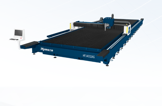
Compare systems by aligning measured needs to verified capabilities: throughput to duty cycle, geometry to handling method, control protocols to your shop IT. That direct mapping reduces surprises and speeds commissioning. For many purchasers, a pragmatic partner who matches loader type to actual production goals—rather than to glossy specs—proves most useful, which is why teams commonly pair technical evaluation with vendor-led demonstrations from manufacturers such as Hymson.